Surge Arrester
Espak Co is working in earthing, lightning arresting and surge protecting from 1975 so far and is the most experienced company in the mentioned fields.
Protecting against lighting is among key and important concepts of protection that this study investigates the necessity of using secondary protection against electromagnetic induction and explains necessities and how to use and select protective surge protector to protect electrical and electronic equipment.
Espak Co is the official agent of HAKEL Co in The Czech Republic and has used this brand in its projects such as 29 airport sites of Iran.
First, key concepts for designing, selecting and installing protection against voltage surge are introduced.
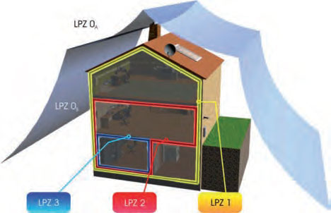
Lightning Protection Areas (LPZ)
IEC 62 305 standard defines LPZ lighting protection areas considering direct and even indirect effect of lightning.
First, we will explain the basic concepts for designing, selecting, and installing overvoltage protection.
| District | Description |
|---|---|
| LPZ0A | Free space without protection with the probability of direct thunder stroke-influenced by not weakened or extreme LEMP waves |
| LPZ0B | Protection against direct thunder stroke- influenced by not weakened LEMP waves (high LEMP) |
| LPZ1 | Inside building (with primary protection)-weakened LEMP waves considering the type of shielding |
| LPZ2 | Inside room (like server room) with conductive floor and meshed floor and wall (with weaker LEMP waves and more effective in connection with shielding surface) |
| LPZ3 | Inside metal box (with the least LEMP waves) |
The article "Earth System" may be interesting to you too!
Nutrition earthing system
Earthing power system aims at preventing the increase of healthy voltages from standard limit and correct and on time performance of protective equipment when error occurs.
Power System Configuration
Generally, different types of earthing low-voltage power system are as follows:
-
System (TN-C-S, TN-S, TN-C) TN
-
System TT
-
System IT

The first letter from left side shows relationship between power system and earth.
T: neutral power transformer is directly connected to earth.
I: no point of power transformer is connected to earth and or it is connected with high impedance.
The second letter from left side shows relationship between consumer conductive shell and earth.
N: consumers conductive shell are connected to earth through earthing system conductor of power source (transformer).
T: consumers conductive shell is not connected to power source earthing system (transformer).
Next letters in TN system:
TN-C refers to using one common conductor as neutral conductor (N) and protective conductor (PE) has been defined as PEN.
TN-S also refers to separately using both conductors as neutral conductors (N) and protective conductors (PE).
1- TN system:
TN system is the most common electrical energy distribution system, neutral point (N) is directly connected to earth in this structure but depending on the type of equipment shell connection to earth and protective wire distribution PE uses three systems called TN-C, TN-S and TN-C-S.
TN-S system
As well as three phase conductors in TN-S system, neutral conductor (N) and protective conductor (PE) also exist separated from each other that these two conductors have been connected to each other in source and are separated in the rest of the path.
Explanation: it passes through neutral conductor of single-phase return flow in TN-S system, it passes through PE conductor in the case of phase connection to shell fault current.
TN-C system
This system is similar to TN-S system in structure although two PE and N conductors are transformed into one PEN conductor (with the least 10 mm2 cross section) in TN-C system to take the responsibility of both conductors.
TN-C-S system
It is a combination of two TN-C and TN-S systems so that TN-C systems used to supply three-phase loads and TN-S systems used to supply single-phase loads.
Explanation: after separating neutral and protective wire from each other (system transformation into TN-S), it is not allowed to connect them to each other again.
2. TT system
Neutral point and equipment shell are connected to earth in TT system. A system is considered TT when the nature of power earthing and the performance of protective elements (keys, fuses and…) are not known. (Or if there is a high PLE distance from equipment to source).
Practically, TT system is simpler than IT and TN systems and it is widely used in European and different countries of the world. This system is dictated due to RCDs where protection against electrocution is very important.
3. IT system
Because of conductors capacitor impedance (Xc) in normal working situation, only a leakage current flows between conductors and earth in this system which depends on the expansion of cable network. This current doesn’t exist in three-phase systems due to symmetry. There is no electrocution in this system with the occurrence of first fault and the system won’t be damaged but protective system acts as a result of second fault due to increase of current.
Neutral wire mustn’t be distributed in IT system as much as it is possible due to:
If neutral connects to earth for any reason, system transforms from IT into TT and TN.
In the case of neutral conductors in this path, protective tool like fuse is predicted for them.
IT system application: since there is no power outage and also no electrocution as a result of first fault (shell or phase connection to earth) in IT system so when power outage isn’t desirable, it is used in operating rooms, metals, glass and… melting furnaces.
Note: IT distribution systems are not popular and used in urban electricity distribution.
Note: since the installation of arresters in TT and TN power systems is different and it is important in protection and lifespan of arresters, it is necessary to first diagnose power earthing systems correctly.
If you need further guidance, you can contact our experienced specialists for information and product purchase.
Surge Protection
In order to control surges conducted by power cables, signals and… have been connected to equipment, it is necessary to use Surge Protector Device (SPD).
Protection system against LEMP which uses protective zoning method suggests installing suitable SPDs in protective zones intervals on conductive lines connected to equipment, so that inrush currents conducted by equipment and surge voltages applied to their terminal are reduced and are less than equipment dielectric breakdown voltage. A coordinated protection needed to control these shocks (surges) by SPDs so that these tools be coordinated with each other considering energy tolerance and the level of their protective voltage is suitable with protected equipment dielectric breakdown.

The reasons of surge voltage occurrence in atmospheric events
Direct impact to building is conducted by building lighting arrester system to earth. Lightning impact to adjacent buildings is transferred to installed buildings and equipment through communicative conductors (entrance service lines, water and gaps pipes, power, and telephone and…).
Clouds electric discharge happened faraway and electromagnetic field resulted from it creates inductive currents and voltages on equipment conductive lines and shell.
Lighting direct discharge on entrance transfer lines to buildings which conducts lighting direct energy into building and its equipment.
Energy of lightning direct impact influences collision point, but its electromagnetic induction effects may cause damages in wide areas which sometimes reaches square kilometers.
Principally, lightning secondary effects which may solely or totally impose shock currents and voltages to structure protected equipment and installations appear as follow:
- Resistive coupling
- Capacitive coupling
- Inductive coupling
Note: voltage surges resulted from power system events and performance are created for the following reasons:
- Capacitor, transformers and cables circuits outage
- Power machines heavy loads connection and disconnection
- Short connection and circuit outage
* Using SPDs in different protective zones (LPZ 1…n) for power lines.
The main danger of lightning is based on the following current parameters:
- Primary main and short impact of lightning (with 10/350µs waveform) with high domain and energy and has the most danger.
- Next short impact (with 0.25/100µs waveform) with high slope but applies less energy to installations.
- Long impact (with long wavelength 1s) applies one extra load on previous impacts to system.
SPDs installed in different points of system and in protective zones intervals have to be able to tolerate all loads resulted from different current parameters, coordinated with each other so that none of them be overloaded.
In order to supply energy coordination among SPDs, the following waveforms have been simulated by their manufacturers:
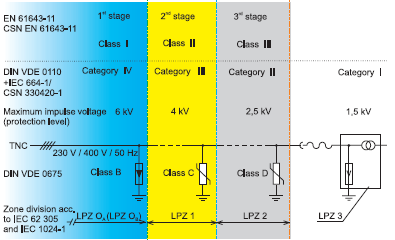
(10/350µs)Iimp: this current test wave (class I) has been defined for PSDs which have to conduct a part of lightning main current to earth. These tools are installed on LPZ0A-1 border.
(8/20µs)In: this current test wave (class II) has been defined for PSDs which have to tolerate inductive and or transit flows from its previous SPDs and conduct them to earth. These tools are installed on LPZ0A-1 and or LPZ1-2 border.
(8/20µs)ICWG: this test wave (class III) is the output of a hybrid generator whose open-circuit voltage is UOC (1.2/50µs) and its virtual resistance is 2Ω and protective devices tested by that are installed on LPZ2-3 border.
Installing PSDs in different points of electricity distribution system and different LPZs
Protective devices tested by 10/350µs (class I) wave have to be “voltage switcher” like spark gaps.
Making air gap, SPD may tolerate a part of lightning direct current without being damaged and transforms transit shock to test wave (8//20µs) for next protector.
PSDs tested by wave (class II) 8/20µs, conduct shock current resided from previous protector towards earth and the level of their protective voltage will be appropriate with protected equipment insulation resistance. Metal Oxide Varistors (MOV) have been used in the main structure of these SPDs.
PSDs tested by mixed wave (voltage 1.2/50µs and current 8/20µs) provide the ultimate level of protection against residual inductive currents and in equipment input terminal with a structure compounded of gas varistors and capsules (GDT).
Energy coordination among SPDs
If SPD installed on LPZ0-1 border be “voltage switcher”, then SPD after “voltage limiter” with varistors building is exposed to main current 10/350µs and is damaged. As soon as several PSDs are serially placed on the path of power like, it is necessary to study coordination among them.
- Energy coordination means that energy passed through every PSD has to be appropriate with (equal or less) the tolerable energy of next protector. These considerations protect equipment and also increase the lifespan of protective system.
- This coordination may be among current/ voltage specifications of two SPDs considering decoupling elements (cable path inductance and or an integrated inductor) and or without needing such elements.
- In order to determine decoupling elements, the rate of current phase growth to time change (di/ dt) is considered. Inductance has been considered as two parallel conductors (phase wire and earth) for every 1µH m that higher values are based on the distance between these two conductors from each other. SPD1 sparking depends on residual voltage SPD2 (Ures) and voltage has two decoupling elements UDE. As soon as U1 exceeded “air gap” sparking voltage, SPD1 acts (MOV specification and shock current slope and decoupling elements inductance will be effective on SPD1 sparking voltage).
When “air gap” type SPD be activated before “MOV” type SPD loses its tolerance against shock current transit and control energy more than “MOV” tolerance, energy has been well coordinated.

- If several “MOV” SPDs be serially placed next to each other and their current/ voltage specification and also their residual voltage be equal, there is no need to decoupling elements and the natural impedance of their communicational lines is coordinator.
- Manufacturers of SPDs announce the conditions of coordination among their products that has to be considered when using them. It is not permissible to use SPDs of different companies due to lack of coordination among different pieces.
If you need further guidance, you can contact our experienced specialists for information and product purchase.
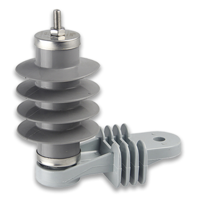
Protective arresters
A- Different types of arresters considering systemic application
- Arrestors for powering systems
- Arrestors for data and signal line
- Arrestors for Rf (radio frequency)
B- Different arrestors considering structure
Voltage switching type SPD (sparker, gas capsule and direct discharge capsule)
It is an arrestor with high impedance in normal condition but when surge happens, its impedance suddenly decreases. Spark gap, GDTs, thyristors and TRIAC are used in the structure of these arrestors.
Voltage limiting type SPD (TVS, MOV and Zener diode)
It is an arrestor with high impedance in normal condition but when surge happens, its impedance continually decreases. Non-linear elements like varistors and diodes are pieces have been used in the structure of such arrestors. These arrestors are sometimes called clamping type.
Comparing advantages and disadvantages of SPDs different structures
| SPD model | Advantages | Disadvantages |
|---|---|---|
| SPARK GAP(SG) | High impulse current capability TOV high tolerance | High protection level follow current |
| Metal Oxide Varistor(MOV) | Low protection level Without follow current | Limited impulse current capability TOV low tolerance |
The following table shows a summary of lightning arrestors performances, orders and necessities.
| Type/Design - Standard | EN 61643-11:2012 | IEC 61643-11:2011 |
|---|---|---|
| Current surge arrester/ hybrid surge arrester | Type 1 SPD | Class 1 SPD |
| Surge arrestor for electrical enclosure, minor electrical enclosure, fixed installations | Type 2 SPD | Class 2 SPD |
| Surge arrestor for sockets/ end devices | Class 3 SPD | Class 3 SPD |
Classification of SPDs based on IEC and EN
Definitions and characteristics of SPDs
Lightning Protection Zone (LPZ)
It is a zone that electromagnetic waves resulted from lightning discharge has been defined for that. These zones have not been physically delimited (wall, floor and roof).
Surge
It refers to a transient wave which is created as a result of Lightning Electromagnetic Impulse (LEMP) as overvoltage and over-instantaneous current. This surges may appear as a part of lightning main current and or electromagnetic induction and or current resided after passing through a protector against surges.
Nominal Voltage, Un
It is related to protected system nominal voltage. This parameter is used for operating voltage of different types of protective arrestors in IT systems. It is shown with rms in AC power.
Max. Continuous Voltage, Uc
The maximum continuous operating voltage (which was previously called nominal voltage), root (square root), RMS are from maximum voltage which may be applied on terminals on wave protective devices during operations.
This maximum voltage applied to lightning arrestor has been defined in non-conductive state (non-operational) which makes sure that this state is recovered after operations and discharge process.
Uc depends on nominal voltage of the system has to be protected and installation standard necessities IEC 60364-5-53 (HD 60364-5-534). Considering 10% voltage tolerance or TN and TT systems, the maximum continuous operational voltage is 256 V for 400/230 V systems.
Nominal Load Current, IL
It refers to the highest allowable current of circuit so that it is permanently applied to the related to terminals.
Max. Discharge Current, Imax
It is the maximum of impulse current peak (20.8 µs waveform) which may be discharged without tolerated arrestor and without damaging arrester.
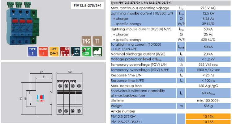
Lighting Impulse Current, limp
This is a standardized impulse current curve with 350.10 µs waveform. Its parameters (peak, load, specific energy) simulate stress resulted from natural lightning currents. Lighting impulse currents (350/10 µs) are applied on type 1 SPDs. They have to discharge such lighting impulse currents for several times without damaging equipment.
Nominal Discharge Current, In
Nominal discharge current In is the peak of a current which passes through SPD. It has 20.8 µs impulse current waveform and has been crated for classification of type 2 SPDs test.
Voltage protection Level, Up
The voltage protection level of a SPD demonstrates the maximum instantaneous voltage in SPD terminals and also specifies their capacity for limiting frequencies to the residual level (in fact, it limits lighting current up to Up level).
Depending on the type of SPD, voltage protection level is determined using the following personal experiments:
- Impulse lighting voltage, 50/1.2 µs (100%)
- Residual voltage Ures in nominal discharge current (according to IEC 61643-11 (EN 61643-11))
Electrical protector device is selected suitable with the place of installation according to overvoltage groups described in IEC 60664-1 (EN 60664-1). Only 2.5 kV is needed for a three-phase system 400.230 for fixed electrical equipment. Equipment supplied in ultimate circuits by these installations need voltage protective level lower than 2.5 kV.
Also IEC 60364-5-53 (HD 60364-5-534) need the minimum level of voltage protection 1.5 kV to install low-voltage consumers 400/230 V for consumers according to overvoltage cat I. This minimum level of voltage protection may be achieved using a type 1 coordinated system and type 2 SPD system or using a type 1 hybrid lightning arrestor.
Also IEC 60364-5-53 (HD 60364-5-534) need the minimum level of voltage protection 1.5 kV to install low-voltage consumers 400/230 V for consumers according to overvoltage cat I. This minimum level of voltage protection may be achieved using a type 1 coordinated system and type 2 SPD system or using a type 1 hybrid lightning arrestor.
- Up in power networks introduces the place of installing arrestor considering coordination with electrical enclosure and equipment insulation voltage.
- Up has to be selected according to protected equipment safety level in IT networks.
Resistance capability against short connection ISCCR
This effective current is power frequency short connection which surge protector device may easily overcome it with upstream support fuse (support protection).
Follow Current Extinguishing Capability Ifi
It is equal to the rms of follow current resulted from input power voltage connection to earth after lightning current discharge which may be automatically distinguished by arrestor.
Back-Up Fuse
It refers to the fuse that it is installed towards power before arrestor to distinguish follow currents with urban electricity frequency when it is higher than arrestor outage capacity.
Hybrid Impulse Wave (UOC)
It is a wave which is produced by a hybrid generator for impulse current and voltage (1.2/50 and 8/20 µs) and by a virtual resistance 2 Ω. The open-circuit voltage of this generator is defined as Uoc which is preferably used for type 3 (class III) arrestors.
Rated Impulse Withstand Voltage Level-Uw
It is a device which is specified by its manufacturer and is demonstrative of device insulation withstand capability to instantaneous overvoltage.
If you need further guidance, you can contact our experienced specialists for information and product purchase.
Selecting surge/current protection devices (Surge Arrester)
In complex and extensive electronic systems, both power and signal circuits must be considered for the correct selection and proper coordination of surge protective devices (SPDs).
Selection based on protective voltage level
The insulation resistance level (Uw) of the protected equipment must be defined according to the following references:
-
At the power supply terminal of equipment complying with IEC60664 standard
-
Equipment immunity level at the signal terminal of the equipment complies with the ITU-T-K20,21 standard.
-
Insulation tolerance level at terminals connected to other lines, based on specifications provided by the manufacturer
Selection based on installation location and discharge flow
A protective device must be able to withstand the expected discharge currents at its installation locations.
1) On the building entrance lines – within the LPZ1 distance – on the main power distribution board of the building
- Installation of a class I surge protective device (SPD), tested with Iimp (10/350µs), so that it can withstand a portion of the main lightning current (10/350µs) according to the values declared for the different protection levels (LPL).
- Installation of a class II surge protective device (SPD), tested with In (8/20µs), so that it can withstand the induced currents on the lines located entirely within the LPZ0B protection zone.
2) The nearest point on the lines connected to the equipment – within the LPZ2 distance and more – on the building’s electrical sub-distribution board or on the equipment’s power supply socket
- Install a surge protective device (SPD class II) tested with In (8/20µs), so that it can withstand the induced current expected in this area (no space or cable shield).
- Install a surge protective device (SPD class III) tested with a combined wave of current In (8/20µs) and voltage Uoc (1.2/50µs), so that it can withstand the induced currents and voltages expected in this area.
Installation conditions for a coordinated protection system
The proper performance of a coordinated protection system depends not only on the choice of the type of protective device (SPD) but also on the correct conditions of their installation:
-
SPD installation location
-
Conductors connected to SPD
-
Protected distance during oscillation phenomenon
-
Protected distance during induction phenomenon
You might also find the article "Sealing Paste" interesting!
General considerations when selecting and installing surge protective devices (SPD)
The selection of protective devices coordinated with each other is done according to their technical specifications and the equipment to be protected, as well as the installation conditions:
Installation of a protective device (SPD1) in class I and at the point of entry of the power lines into the building in the main switchboard
1- Determining the insulation tolerance level of the protected devices (UW)
2- Selecting a suitable protective device whose UP1 is less than the insulation tolerance of the device (UW)
3- The distance between the protected cable and the device is appropriate.
If two cases 3 and 4 are not met, then another protective device (SPD2) must also be used:
4- Install another protective device (SPD2) whose energy is coordinated with (SPD1) near the protected device (within the distance of the LPZ2 protection zone or in the sub-power switchboard).
5- Selecting a protective device so that its UP2 is less than the Uw of the device and provides effective protection.
6- The distance of the protected cable to the device is appropriate.
If two cases 6 and 7 are not met, then it is necessary to install a third protective device (SPD3) at the closest point to the protected device (device power outlet) and in coordination with SPD2, SPD1.
Protection of telecommunications equipment connected to RF lines against voltage surges caused by lightning
Telecommunications are of particular importance in today's world. The enormous costs paid for the purchase of information equipment, as well as the efforts of specialized personnel in the installation, operation, and maintenance of the above facilities, require that the reception and distribution of signals have the highest quality standards and that signal interruptions are reduced as much as possible. Today, telecommunications equipment (including microwaves, satellites, mobile radio systems, wireless, etc.) is exposed to unpredictable weather events and, in addition to extensive financial losses, also suffers from communication interruptions that are sometimes irreparable. It is hoped that trying to provide solutions to reduce the damage caused by lightning to such systems will be able to remind us of the importance of protecting information transmission by coaxial cables and, subsequently, protecting the relevant electronic equipment against induced overvoltages.
Lightning protection standards for RF equipment
Surge suppression for RF equipment is very different from the protection of low frequency electrical and telecommunications equipment.
In particular, in the protection of such equipment, capacitive coupling between the signal and ground must be minimized to prevent RF signal loss. For this reason, the use of varistors and semiconductor diodes is excluded in this case.
The following two principles are used to design the various components of a coaxial cable protector for RF equipment:
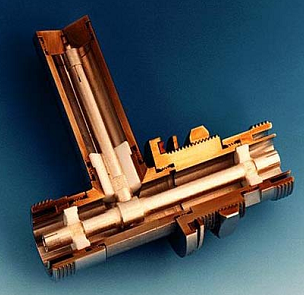
A- Gas Capsules Protectors
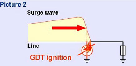
In the event of an overvoltage, the gas capsule located between the inner and outer conductors (shield) of the coaxial cable will ignite and thus become at the same potential as the ground system. Therefore, this system is like a switch that is turned on and off by the voltage surge caused by lightning.
In this design, special gas-filled capsules are installed in the signal path, which are abbreviated as SPD.
If lightning strikes the antenna or antenna support of a receiver (or transmitter), a current flows to the receiver (or transmitter). Part of this current is transferred directly to the ground through the antenna support, and the other part is grounded through the RF cable and the arresters mounted on it at the interface between the RF cable and the transmitter (or receiver).
It is also possible that a lightning strike to the ground near the receiving (or transmitting) station induces a voltage on the RF line and ultimately sends a current to the equipment, in which case the arresters (SPD) mounted on the line act as a low-resistance element and ground the overvoltage caused by the induction, so that the capsules used in the protectors spark (by reducing their resistance) and cause the signal conductor to become equipotential with the cable shield, and as a result, the lightning current and energy are directed to the ground.
It should be tried to discharge the lightning current outside the equipment and building. Therefore, it is necessary to install a protective device outside the building to prevent the induction of overvoltage on the equipment inside the protected area.
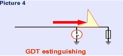
After the shock is removed, the gas capsule returns to its normal working conditions and, in other words, it again finds the role of a high-resistance element and the system will continue to work as before the lightning strike.
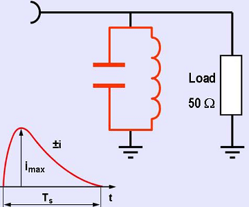
To understand how this method works and compare it to other methods, let’s examine the operation of a gas capsule.
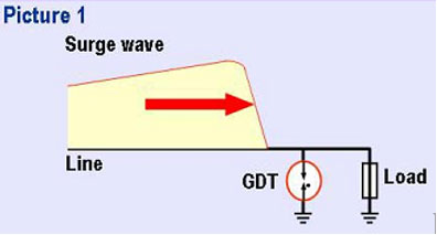
Here, the LOAD is the electronic device that needs to be protected and the SPD (protective device) is the gas capsule. The capsule consists of two electrodes insulated by a ceramic housing. The type and pressure of the gas inside the capsule, along with the distance between the electrodes, determines the static spark voltage.
During interference and disturbance (as a product of lightning), a current moves through the cable towards the device, which is shown as an attack wave in the image below.
At this time, the voltage across the capsule increases rapidly, and when it reaches the dynamic spark voltage, the capsule electrodes spark and the space between them becomes conductive. The voltage across the capsule, which is called the open spark voltage in this case, is about 72 to 90 volts (depending on the type of capsule) and decreases to 10 to 20 volts with greater conductivity and increasing current. The dynamic spark voltage of a capsule is a function of the induction pulse growth time.
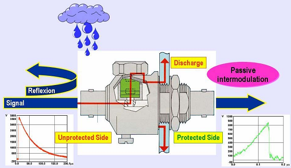
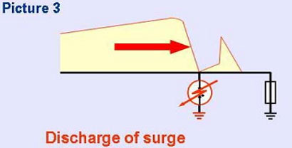
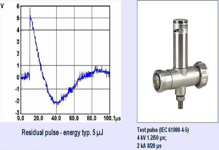
When the protective capsule ignites, the signal conductor and the outer conductor (shield/ground) of the transmission line are equipotentialized and the impulse current flows through the path of least resistance, which is the protective capsule, to the ground. Only a very small portion of the energy, called the residual pulse, will reach the device. The amount of residual energy is determined by the type of capsule, the growth time of the attack pulse, and the impedance of the ground in which the discharge occurs.
* After the attack wave subsides, the shielding capsule is turned off and returns to its initial high-resistance state. Gas shielding capsules are used in a wide frequency range from DC-2.5 GHZ.
* The upper limit of the operating frequency is determined by the capacitive properties of the capsule in question. Shielding capsules allow the passage of DC waves and allow the use of amplifiers through coaxial cable.
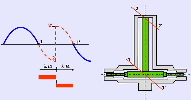
B- Protector with shorting stub λ/4
This technology is based on a ¼ wavelength of the transmitted signal. In this case, a stub is placed in the path exactly like the corresponding coaxial cable (shorted at its end), the length of which is proportional to the intermediate frequency, its frequency band, and thus plays the role of a band-pass filter. The bandwidth is 2-20% depending on its specific design.
Protector with shorting stub λ/4
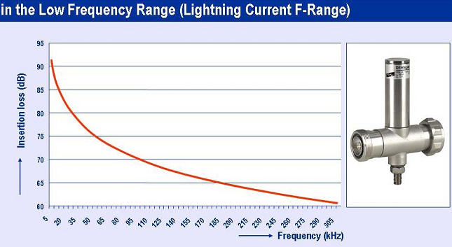
Since the induced waves caused by lightning have a low frequency spectrum (up to 100KHZ), the spur acts as a short circuit with the ground and directs the shock currents towards it.
The principle of transmitting RF signals through a λ/4 interference suppression element is as follows:
In normal operation of the system, the RF signal reaches the input point (point 1) and travels along the spur to point (2), where it has found a 90 degree phase difference. At point 2 (the short circuit point), the wave is reflected and a sudden phase difference of 180 degrees is created before it returns to the starting point (point '1'). This return will also cause another phase difference of 90 degrees, and as a result the reflected wave is again in phase with the incoming wave. In this case, the short-term RF interruption (during the grounding of lightning shocks) will not be noticeable. These protectors have a narrower bandwidth compared to gas protectors, with a frequency band of up to 20% (± 10% relative to the center frequency), but are capable of withstanding much higher currents and provide a significant reduction in residual ripple.
• The working principle of this type of protector allows them to be manufactured from a few MHz to 20 GHz. They are designed in such a way that they show the least intermodulation effects (as a nonlinear element) in transmission lines and due to the lack of maintenance, they have found wide application in RF engineering.
The residual wave in this protector (voltage and energy) is significantly reduced compared to its gas type.
Unlike its gas type, this protector will not be able to transmit any dc wave (because the signal conductor and shield are connected to each other and to ground).
The frequency range of this protector is determined by the geometric limitations of the construction (in terms of the length of the protrusion).
Residual pulse energy and RF arrestor
In order to make sure of correct performance of (EMP-PRO) arrestor and decreasing residual voltages, the following considerations have to be used when installing a protective system:
- During installation, protective equipment has to be connect to devices georeferenced point. Then, an unsuitable system with earth loops, earth conductors small cross-sections and weak connections may increase residual energy after protection.
One of the suitable methods is installing bulk head on wall and outside space interval and inside equipment room which all cables enterd internal space passing through it and are protected by arrestors installed on this sheet. This sheet will be connected to earth electrodes network by suitable cables and copper straps. - Earth connection points have to electrically conductive (connection points have to be clean of any pollution and dust).
- The least defined torque for bolted joints (nu manufacturing company) is considered when fixing pieces to minimize contact resistance.
- Protective system components have to be installed in unprotected zones to prevent the creation of inductive voltages (inductive coupling) on conductors and cables connected to equipment.
SPDs for Information Technology System
Different standards have highly emphasized on the necessity of using protective equipment to protect measurement, telecommunicational, data and control against overvoltage systems.
International standard IEC 61312-1 represents all needs and demands according to zone concept.
According to this standard, using suitable protectors at different levels of energy have been recommended to protect information and telecommunicational systems against LEMP.
Lightning arrester price
To find out the prices of various types of lightning arresters or surge arresters from Espak Iran Company, you can contact our experienced consultants and experts so that you can choose the best product for the space and environment you need.